Heathkit IO 4550: Difference between revisions
m (→Vertical Circuit Board (85-1989-2): PCB ID Formatting) |
(Formatting updates and improvements) |
||
| (7 intermediate revisions by 3 users not shown) | |||
| Line 9: | Line 9: | ||
|Batteries = None | |Batteries = None | ||
|Destructive Entry = No | |Destructive Entry = No | ||
}} | |Input Voltage=Mains voltage - region specific (non-universal)}} | ||
The Heathkit IO 4550 is a dual trace 10 MHz oscilloscope sold as a kit for the end user to assemble themselves. | The Heathkit IO 4550 is a dual trace 10 MHz oscilloscope sold as a kit for the end user to assemble themselves. | ||
== Known Issues == | == Known Issues == | ||
=== Unit emits smoke and/or a loud bang when powered on === | === Unit emits smoke and/or a loud bang when powered on === | ||
==== Cause ==== | ==== Cause ==== | ||
*Several tantalum capacitors on the power rails fail short circuit | *Several tantalum capacitors on the power rails fail short circuit | ||
| Line 22: | Line 18: | ||
File:Short circuit tantalum.jpg|alt=Visible and thermal images of a tantalum capacitor that has failed short circuit|Visible and thermal images of a tantalum capacitor that has failed short circuit | File:Short circuit tantalum.jpg|alt=Visible and thermal images of a tantalum capacitor that has failed short circuit|Visible and thermal images of a tantalum capacitor that has failed short circuit | ||
</gallery> | </gallery> | ||
==== Solution ==== | ==== Solution ==== | ||
*Replace all faulty tantalum capacitors on the | *Replace all faulty (and not yet faulty) tantalum capacitors on the ±15 V rails and repair any other damage. eg. burnt PCB traces or shut regulator power resistors. | ||
== Disassembly Notes == | == Disassembly Notes == | ||
{{WarnAlt|danger|med|This device contains a high voltage electrostatically deflected [[CRT Repairs|CRT]] with fully exposed high voltage PCBs.}} | |||
{{WarnAlt|warning|med|This device contains a fully exposed open frame [[Mains Power|mains voltage]] power supply.}} | |||
*It is recommended you power the +/- 15 V rails with an external bench power supply prior to plugging the device into mains to be able to limit the current draw to prevent damage to shunt regulators from shorted tantalum capacitors. | *It is recommended you power the +/- 15 V rails with an external bench power supply prior to plugging the device into mains to be able to limit the current draw to prevent damage to shunt regulators from shorted tantalum capacitors. | ||
* The PCB does not need to be removed from the chassis to replace capacitors, it is difficult to desolder/solder some capacitors with the board still in the chassis | *The PCB does not need to be removed from the chassis to replace capacitors, while it is difficult to desolder/solder some capacitors with the board still in the chassis, in order to remove the PCB a number of flying leads and the front panel knobs have to be removed which is difficult and time consuming. | ||
== Original Parts == | == Original Parts == | ||
=== Vertical Circuit Board === | === Vertical Circuit Board === | ||
| Line 42: | Line 30: | ||
''85-1989-2'' | ''85-1989-2'' | ||
While Healthkit devices come with an assembly manual and components list unfortunately digitized versions on the internet are missing page 27 which contains information about those faulty tantalum capacitors. | While Healthkit devices come with an assembly manual and components list unfortunately digitized versions on the internet are missing page 27 which contains information about those faulty tantalum capacitors. This unit also included orange tantalum capacitors on other PCBs in the unit however those tested good. The failure of this unit was while it was in the hands of the previous owner, it failed slowly overheating and damaging resistors that form part of a shunt regulator until it failed catastrophically, the previous owner had unsuccessfully attempted a repair by only replacing the one tantalum capacitor that had burnt the PCB before exploding. | ||
{| class="wikitable" | {| class="wikitable" | ||
|+Capacitor [[Capacitor Specifications|Specifications]] and | |+Capacitor [[Capacitor Specifications|Specifications]] and [[Part Footprints|Footprint]] Information | ||
!RefDes | !RefDes | ||
!Qty | !Qty | ||
| Line 61: | Line 48: | ||
|Tantalum | |Tantalum | ||
|KEMET | |KEMET | ||
|- | |||
| | |||
|7 | |||
|1000 μF | |||
|35 V | |||
|Through Hole | |||
|Aluminum Electrolytic | |||
|Rubycon | |||
|} | |||
=== Horizontal Circuit Board === | |||
{| class="wikitable sortable" | |||
|+Capacitor [[Capacitor Specifications|Specifications]] and [[Part Footprints|Footprint]] Information | |||
!RefDes | |||
!Qty | |||
!Capacitance | |||
!Voltage | |||
![[Part Footprints|Mount]] | |||
!Diameter/Size | |||
!Height | |||
!Lead Spacing | |||
!Temp | |||
![[Capacitor Types|Type]] | |||
!Brand | |||
!Series | |||
|- | |||
| | |||
| | |||
|100 µF | |||
|100 V | |||
|Through Hole Axial | |||
| | |||
| | |||
| | |||
|0 °C | |||
| | |||
| | |||
| | |||
|} | |} | ||
==Replacement Parts== | ==Replacement Parts== | ||
===Vertical Circuit Board=== | ===Vertical Circuit Board=== | ||
| Line 69: | Line 92: | ||
Note that those capacitors are not in critical analog parts of the oscilloscope circuit but are used for power rail bulk capacitance. As a result you can pretty much substitute any modern 10 μF 20 V capacitor, I used wet electrolytics that were laying around as the unit is unlikely to be used much, however below are some equivalent tantalum capacitors that should be considered if doing a proper restoration. | Note that those capacitors are not in critical analog parts of the oscilloscope circuit but are used for power rail bulk capacitance. As a result you can pretty much substitute any modern 10 μF 20 V capacitor, I used wet electrolytics that were laying around as the unit is unlikely to be used much, however below are some equivalent tantalum capacitors that should be considered if doing a proper restoration. | ||
{| class="wikitable" | {| class="wikitable" | ||
|+Capacitors | |+Capacitors | ||
| Line 79: | Line 101: | ||
|C114-1, C114-2, C115-1, C115-2, C116-1, C116-2, C123-1, C123-1, C124-1, C124-2 | |C114-1, C114-2, C115-1, C115-2, C116-1, C116-2, C123-1, C123-1, C124-1, C124-2 | ||
|10 | |10 | ||
|T356E106K020AT | |T356E106K020AT / TAP106M035SCS / TAP106K035SCS | ||
|[https://www.digikey.com/en/products/detail/kemet/T356E106K020AT/818500 | |[https://www.digikey.com/en/products/detail/kemet/T356E106K020AT/818500 DigiKey] [https://www.mouser.com/ProductDetail/KYOCERA-AVX/TAP106M035SCS?qs=sGAEpiMZZMtZ1n0r9vR22f0Jgorj1M1uLTL5%252BhlrlUk%3D Mouser] [https://www.lcsc.com/product-detail/Tantalum-Capacitors_Kyocera-AVX-TAP106K035SCS_C73787.html LCSC] | ||
|- | |||
| | |||
|7 | |||
|35PX1000MEFC10X20 / UVR1V102MHD1TO / EKY-350ETD102MK25S | |||
|[https://www.digikey.com/en/products/detail/rubycon/35PX1000MEFC10X20/3563769 DigiKey] [https://www.mouser.com/ProductDetail/Nichicon/UVR1V102MHD1TO?qs=GsRI6e%2FkDqaxg%2FkU%252BUf9rg%3D%3D Mouser] [https://www.lcsc.com/product-detail/Aluminum-Electrolytic-Capacitors-Leaded_NCC-Nippon-Chemi-Con-EKY-350ETD102MK25S_C337467.html LCSC] | |||
|} | |||
=== Horizontal Circuit Board === | |||
{| class="wikitable sortable" | |||
|+Capacitors | |||
!RefDes | |||
!Qty | |||
!Compatible Part Number | |||
!Order Links | |||
|- | |||
| | |||
|1 | |||
|107TMA100M | |||
|[https://www.digikey.com/en/products/detail/cornell-dubilier-illinois-capacitor/107TMA100M/5410809 DigiKey] [https://www.mouser.com/ProductDetail/Cornell-Dubilier-CDE/107TTA100M?qs=3tP%252BN51vMXd0iKsJmSq4fA%3D%3D Mouser] | |||
|} | |} | ||
''If parts are not available or different selection is preferred, you can use the values in the [[Heathkit IO 4550#Original Parts|Original Parts]] section to perform a parametric search.'' | ''If parts are not available or different selection is preferred, you can use the values in the [[Heathkit IO 4550#Original Parts|Original Parts]] section to perform a parametric search.'' | ||
== References == | == References == | ||
<references /> | <references /> | ||
[[Category:1970s]] | [[Category:1970s]] | ||
[[Category:Oscilloscope]] | [[Category:Oscilloscope]] | ||
[[Category:Test Gear]] | |||
[[Category:CRT]] | |||
Latest revision as of 08:22, 28 July 2024
| Preliminary Information | |
|---|---|
| Release Year | 1978 |
| Leak Risk | Unknown |
| Batteries | None |
| Mounting Technology | Through Hole, DIP Sockets, Flying Lead |
| Capacitor Types | Electrolytic, Tantalum, Paper, Ceramic, Polymer, Mylar, Mica |
| Destructive Entry | No |
| Power Requirements | |
| Input Voltage | Mains voltage - region specific (non-universal) |
| CRT Guides | |
| General Information · Repair Cautions | |
The Heathkit IO 4550 is a dual trace 10 MHz oscilloscope sold as a kit for the end user to assemble themselves.
Known Issues
Unit emits smoke and/or a loud bang when powered on
Cause
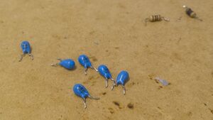
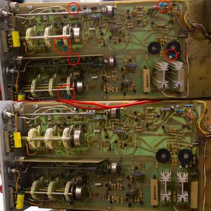
- Several tantalum capacitors on the power rails fail short circuit
-
Visible and thermal images of a tantalum capacitor that has failed short circuit
Solution
- Replace all faulty (and not yet faulty) tantalum capacitors on the ±15 V rails and repair any other damage. eg. burnt PCB traces or shut regulator power resistors.
Disassembly Notes
- It is recommended you power the +/- 15 V rails with an external bench power supply prior to plugging the device into mains to be able to limit the current draw to prevent damage to shunt regulators from shorted tantalum capacitors.
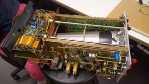
- The PCB does not need to be removed from the chassis to replace capacitors, while it is difficult to desolder/solder some capacitors with the board still in the chassis, in order to remove the PCB a number of flying leads and the front panel knobs have to be removed which is difficult and time consuming.
Original Parts
Vertical Circuit Board

85-1989-2
While Healthkit devices come with an assembly manual and components list unfortunately digitized versions on the internet are missing page 27 which contains information about those faulty tantalum capacitors. This unit also included orange tantalum capacitors on other PCBs in the unit however those tested good. The failure of this unit was while it was in the hands of the previous owner, it failed slowly overheating and damaging resistors that form part of a shunt regulator until it failed catastrophically, the previous owner had unsuccessfully attempted a repair by only replacing the one tantalum capacitor that had burnt the PCB before exploding.
| RefDes | Qty | Capacitance | Voltage | Mount | Type | Brand |
|---|---|---|---|---|---|---|
| C114-1, C114-2, C115-1, C115-2, C116-1, C116-2, C123-1, C123-1, C124-1, C124-2 | 10 | 10 μF | 20 V | Through Hole | Tantalum | KEMET |
| 7 | 1000 μF | 35 V | Through Hole | Aluminum Electrolytic | Rubycon |
Horizontal Circuit Board
| RefDes | Qty | Capacitance | Voltage | Mount | Diameter/Size | Height | Lead Spacing | Temp | Type | Brand | Series |
|---|---|---|---|---|---|---|---|---|---|---|---|
| 100 µF | 100 V | Through Hole Axial | 0 °C |
Replacement Parts
Vertical Circuit Board

85-1989-2
Note that those capacitors are not in critical analog parts of the oscilloscope circuit but are used for power rail bulk capacitance. As a result you can pretty much substitute any modern 10 μF 20 V capacitor, I used wet electrolytics that were laying around as the unit is unlikely to be used much, however below are some equivalent tantalum capacitors that should be considered if doing a proper restoration.
| RefDes | Qty | Compatible Part Number | Order Links |
|---|---|---|---|
| C114-1, C114-2, C115-1, C115-2, C116-1, C116-2, C123-1, C123-1, C124-1, C124-2 | 10 | T356E106K020AT / TAP106M035SCS / TAP106K035SCS | DigiKey Mouser LCSC |
| 7 | 35PX1000MEFC10X20 / UVR1V102MHD1TO / EKY-350ETD102MK25S | DigiKey Mouser LCSC |
Horizontal Circuit Board
| RefDes | Qty | Compatible Part Number | Order Links |
|---|---|---|---|
| 1 | 107TMA100M | DigiKey Mouser |
If parts are not available or different selection is preferred, you can use the values in the Original Parts section to perform a parametric search.
