Studer D741: Difference between revisions
Jump to navigation
Jump to search
(Disassembly Notes) |
|||
| Line 2: | Line 2: | ||
{{InfoboxDevice | {{InfoboxDevice | ||
|Title = Studer D741 | |Title = Studer D741 | ||
|Picture = | |Picture =Studer D741 Front.jpg | ||
|Release Year = 1996 | |Release Year = 1996 | ||
|Mounting Technology = Through Hole, SMD, Sockets | |Mounting Technology = Through Hole, SMD, Sockets | ||
| Line 18: | Line 18: | ||
*Flat head Screwdriver | *Flat head Screwdriver | ||
===Disassembly=== | ===Disassembly=== | ||
==== Top Cover ==== | ==== Top Cover ==== | ||
*Disconnect unit from mains | *Disconnect unit from mains | ||
*Remove 3 screws at the top of the unit, 2 screws on each side, and 3 screws at the upper edge of the rear panel | *Remove 3 screws at the top of the unit, 2 screws on each side, and 3 screws at the upper edge of the rear panel | ||
*Lift the rear of the top cover and slide it to the rear until it comes off | *Lift the rear of the top cover and slide it to the rear until it comes off | ||
==== Main logic board ==== | ==== Main logic board ==== | ||
* Disconnect all wire harnesses from board. Take care not to damage the thin gauge wires | * Disconnect all wire harnesses from board. Take care not to damage the thin gauge wires | ||
* Remove 12 hex screws securing XLR connectors at rear | * Remove 12 hex screws securing XLR connectors at rear | ||
| Line 32: | Line 29: | ||
* Remove 5 hex screws securing the logic board | * Remove 5 hex screws securing the logic board | ||
* Carefully lift the logic board from the chassis | * Carefully lift the logic board from the chassis | ||
==== Power Supply ==== | ==== Power Supply ==== | ||
* Disconnect all wire harnesses from board. | * Disconnect all wire harnesses from board. | ||
* Remove 1 hex screw holding ground bond wire | * Remove 1 hex screw holding ground bond wire | ||
| Line 41: | Line 36: | ||
* Remove 3 hex screws securing board to chassis | * Remove 3 hex screws securing board to chassis | ||
* Carefully lift the board from the chassis | * Carefully lift the board from the chassis | ||
== Original Parts == | == Original Parts == | ||
=== Main Logic Board === | === Main Logic Board === | ||
| Line 225: | Line 219: | ||
== Additional Images == | == Additional Images == | ||
<gallery> | <gallery> | ||
File:Studer D741 Inside.jpg|Top cover removed | |||
File:Studer D741 Main Logic Board.jpg|Main logic board | File:Studer D741 Main Logic Board.jpg|Main logic board | ||
File:Studer D741 Main Logic Board Rear.jpg|Backside of main logic board | File:Studer D741 Main Logic Board Rear.jpg|Backside of main logic board | ||
File:Studer D741 Power Supply.jpg|Power Supply | File:Studer D741 Power Supply.jpg|Power Supply | ||
File:Studer D741 Rear IO.jpg|Rear I/O | |||
</gallery> | </gallery> | ||
== Related Links == | == Related Links == | ||
Revision as of 02:32, 2 February 2023
| This device is in the WorkNeeded:OriginalParts category because it was flagged as missing information on the original parts. It may have replacement parts listed but those cannot be assumed to be identical to the originals. If you have a list of the original parts, please feel free to add them by copying the relevant table from EditorsToolbox:Tables |
| This device is in the WorkNeeded:General category because it was flagged as missing general information about the device. The information may be incomplete, using default text, or inaccurate and should be verified with external sources if possible. If you can add or correct information on this page, please feel free to edit it and do so. |
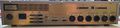
Studer D741

| Preliminary Information | |
|---|---|
| Release Year | 1996 |
| Leak Risk | Low |
| Batteries | None |
| Mounting Technology | Through Hole, SMD, Sockets |
| Capacitor Types | Aluminum Electrolytic, Ceramic |
| Destructive Entry | No |
The Studer D741 is a broadcast grade, 2U rack-mountable CD recorder and player.
Disassembly Notes
Tools Needed
- 3/16 Hex Driver
- 2.5mm Hex Key
- Phillips Screwdriver PH1
- Flat head Screwdriver
Disassembly
Top Cover
- Disconnect unit from mains
- Remove 3 screws at the top of the unit, 2 screws on each side, and 3 screws at the upper edge of the rear panel
- Lift the rear of the top cover and slide it to the rear until it comes off
Main logic board
- Disconnect all wire harnesses from board. Take care not to damage the thin gauge wires
- Remove 12 hex screws securing XLR connectors at rear
- Remove 4 standoffs securing D-SUB connectors to chassis
- Remove 1 Phillips screw securing SPDIF connectors to chassis
- Remove 5 hex screws securing the logic board
- Carefully lift the logic board from the chassis
Power Supply
- Disconnect all wire harnesses from board.
- Remove 1 hex screw holding ground bond wire
- Remove 2 flat-head and 2 hex screws securing metal plate to heatsink
- Remove 2 hex screws securing IEC connector to chassis
- Remove 3 hex screws securing board to chassis
- Carefully lift the board from the chassis
Original Parts
Main Logic Board
Note model numbers and board revisions here
| RefDes | Qty | Capacitance | Voltage | Mount | Diameter/Size | Height | Lead Spacing | Temp | Type | Brand | Series |
|---|---|---|---|---|---|---|---|---|---|---|---|
| 2254, 2255, 2430, 2431, 2432, 2433, 2522, 2523, 2524, 2525, 2526, 2527 | 12 | 100 µF | 16V | Through Hole | 10mm | 13mm | 85 °C | Aluminum Electrolytic | Nichicon | MUSE BP | |
| 2243, 2245, 2251, 2253, 2425, 2427, 2428, 2462, 2463, 2464, 2465, 2466, 2467, 2468, 2469, 2480, 2481, 2482, 2483, 2484, 2485, 2486, 2487, 2488, 2489, 2490, 2491 | 27 | 100 µF | 25V | Through Hole | 6mm | 16mm | 85 °C | Aluminum Electrolytic | Nichicon | VX | |
| 2017, 2018, 2025, 2028, 2031, 2034, 2036, 2038, 2101, 2102, 2104, 2111, 2126, 2150, 2200, 2210, 2214, 2218, 2233, 2236, 2302, 2308, 2312, 2315, 2395, 2396, 2397, 2398, 2472, 2473 | 30 | 47 µF | 25V | Through Hole | 5mm | 12mm | 85 °C | Aluminum Electrolytic | Nichicon | VX | |
| 2016, 2022, 2216, 2220, 2231, 2235, 2343 | 7 | 10 µF | 50V | Through Hole | 5mm | 12mm | 85 °C | Aluminum Electrolytic | Nichicon | VX |
Power Supply
| RefDes | Qty | Capacitance | Voltage | Mount | Diameter/Size | Height | Lead Spacing | Temp | Type | Brand | Series |
|---|---|---|---|---|---|---|---|---|---|---|---|
| 2529, 2530 | 2 | 1000 µF | 16V | Through Hole | 10mm | 20mm | 85 °C | Aluminum Electrolytic | Panasonic | SU | |
| 2515, 2524 | 2 | 1000 µF | 25V | Through Hole | 12mm | 25mm | 105 °C | Aluminum Electrolytic | Nichicon | PF | |
| 2502, 2517, 2526, 2534 | 4 | 47 µF | 35V | Through Hole | 6mm | 10mm | 85 °C | Aluminum Electrolytic | Nichicon | VX | |
| 2535 | 1 | 3.3 nF | 400V | Through Hole | Ceramic | ||||||
| 2503, 2504, 2505 | 3 | 2200 µF | 50V | Through Hole | 18mm | 35mm | 85 °C | Aluminum Electrolytic | Nichicon | VX | |
| 2533 | 1 | 470 µF | 50V | Through Hole | 12mm | 20mm | 85 °C | Aluminum Electrolytic | Panasonic | SU |
Replacement Parts
Basic PCB Name
| RefDes | Qty | Compatible Part Number | Order Links |
|---|---|---|---|
| Digikey |
If parts are not available or different selection is preferred, you can use the values in the Original Parts section to perform a parametric search.
Kits
- Digikey BOM: https://www.digikey.com/
Additional Images
-
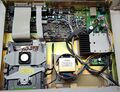
Top cover removed
-
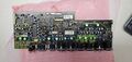
Main logic board
-
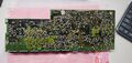
Backside of main logic board
-
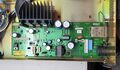
Power Supply
-
Rear I/O


