Actiontec GT704-WG: Difference between revisions
(Created page with "{{WikipediaInfoAlt|Device}} {{DeviceAlerts}} {{InfoboxDevice |Title = New Device |Picture =Actiontecgt704WG-Top.jpg |Release Year = ~2005 |Mounting Technology = Through Hole, SMD, BGA, Sockets |Capacitor Types = Aluminum Electrolytic, Tantalum, Ceramic, Polymer |Leak Risk = High |Batteries = None |Destructive Entry = No }} The Actiontec GT704-WG is a combination DSL modem, Ethernet switch, and Wi-Fi modem. It supports the IEEE standards 802.3 (10BaseT), 802.3u (100BaseT...") |
No edit summary |
||
| Line 24: | Line 24: | ||
==Original Parts== | ==Original Parts== | ||
===Main Board=== | ===Main Board=== | ||
''GT704WG(Verizon) | ''GT704WG(Verizon) P1GT704WG60302'' | ||
F/W: 3.220.3.3.5.0.9.1.3 CS=41B3 | |||
F/W: 3.220.3.3.5.0.9.1.3 | [[File:ActiontecGT704WGpcb.jpg|alt=Main PCB|thumb|Main PCB]] | ||
Sticker on U104: 000FB3 B59428 | Sticker on U104: 000FB3 B59428 | ||
{| class="wikitable sortable" | {| class="wikitable sortable" | ||
| Line 46: | Line 45: | ||
|C1, C3, C4, C13, C47, C62, C64, C80 | |C1, C3, C4, C13, C47, C62, C64, C80 | ||
|8 | |8 | ||
|10 | |10 µF | ||
|25 V | |25 V | ||
|Through Hole Radial | |Through Hole Radial | ||
| Line 59: | Line 58: | ||
|C406 | |C406 | ||
|1 | |1 | ||
|2200 | |2200 µF | ||
|25 V | |25 V | ||
|Through Hole Radial | |Through Hole Radial | ||
| Line 85: | Line 84: | ||
|C424, C446 | |C424, C446 | ||
|2 | |2 | ||
|470 | |470 µF | ||
|10 V | |10 V | ||
|Through Hole Radial | |Through Hole Radial | ||
| Line 98: | Line 97: | ||
|C425*, C427* | |C425*, C427* | ||
|2 | |2 | ||
|330 | |330 µF | ||
|6.3 V | |6.3 V | ||
|Through Hole Radial | |Through Hole Radial | ||
| Line 111: | Line 110: | ||
|C69, C70, C71, C72, C150 | |C69, C70, C71, C72, C150 | ||
|5 | |5 | ||
| | |1000 pF | ||
|2000 V | |2000 V | ||
|Through Hole Radial | |Through Hole Radial | ||
| Line 123: | Line 122: | ||
|} | |} | ||
<nowiki>*:</nowiki> Already bulged on my unit. C427 blew its bottom bung off. | <nowiki>*:</nowiki> Already bulged on my unit. C427 blew its bottom bung off. | ||
==Replacement Parts== | ==Replacement Parts== | ||
=== | ===Main PCB=== | ||
{| class="wikitable sortable" | {| class="wikitable sortable" | ||
|+Capacitors | |+Capacitors | ||
| Line 141: | Line 139: | ||
===Kits=== | ===Kits=== | ||
*Digikey BOM: https://www.digikey.com/ | *Digikey BOM: https://www.digikey.com/ | ||
== Device Photos == | |||
<gallery> | |||
File:Actiontecgt704WG-Top.jpg|alt=Top of Actiontec GT704WG|Top of modem | |||
File:ActiontecGT704WG-Bottom.jpg|alt=Bottom of Actiontec GT704WG|Bottom of Modem | |||
File:ActiontecGT704WG-Front.jpg|alt=Front of Actiontec GT704WG|Front of Modem | |||
File:ActiontecGT704WG-Back.jpg|alt=Back of Actiontec GT704WG|Back of modem | |||
</gallery> | |||
==Related Links== | ==Related Links== | ||
*[https://www. | *[https://www.manualslib.com/manual/526037/Actiontec-Gt704wg.html Manual] | ||
==References== | ==References== | ||
<references /> | <references /> | ||
Revision as of 16:51, 22 April 2023
- For more information, see this article's corresponding Wikipedia page: Device.
| This device is in the WorkNeeded:OriginalParts category because it was flagged as missing information on the original parts. It may have replacement parts listed but those cannot be assumed to be identical to the originals. If you have a list of the original parts, please feel free to add them by copying the relevant table from EditorsToolbox:Tables |
| This device is in the WorkNeeded:General category because it was flagged as missing general information about the device. The information may be incomplete, using default text, or inaccurate and should be verified with external sources if possible. If you can add or correct information on this page, please feel free to edit it and do so. |

| Preliminary Information | |
|---|---|
| Release Year | ~2005 |
| Leak Risk | High |
| Batteries | None |
| Mounting Technology | Through Hole, SMD, BGA, Sockets |
| Capacitor Types | Aluminum Electrolytic, Tantalum, Ceramic, Polymer |
| Destructive Entry | No |
The Actiontec GT704-WG is a combination DSL modem, Ethernet switch, and Wi-Fi modem. It supports the IEEE standards 802.3 (10BaseT), 802.3u (100BaseTX), and 802.11g (wireless). Other standards support includes G.dmt, G.lite, t1.413, and RFC 1483, 2364, and 2516.
See page 108 of the manual for full specifications.
Known Issues
Instability
Causes
- Bad capacitors
Solutions
- Recap Bad capacitors
Disassembly Notes
First, flip the unit upside down. You will see 4 rubber feet. Remove the rubber feet. Under that you will see 4 Phillips (crosshead) screws. Unscrew the 4 screws. After this, the top and bottom should separate. Remove the circuit board (the antenna connector should come with it).
Original Parts
Main Board
GT704WG(Verizon) P1GT704WG60302 F/W: 3.220.3.3.5.0.9.1.3 CS=41B3

Sticker on U104: 000FB3 B59428
| RefDes | Qty | Capacitance | Voltage | Mount | Diameter/Size | Height | Lead Spacing | Temp | Type | Brand | Series |
|---|---|---|---|---|---|---|---|---|---|---|---|
| C1, C3, C4, C13, C47, C62, C64, C80 | 8 | 10 µF | 25 V | Through Hole Radial | 105 °C | Aluminum Electrolytic | CapXon | SZ | |||
| C406 | 1 | 2200 µF | 25 V | Through Hole Radial | 105 °C | Aluminum Electrolytic | CapXon | KM | |||
| C413* | 1 | 1000 µF | 16 V | Through Hole Radial | 105 °C | Aluminum Electrolytic | CapXon | GF | |||
| C424, C446 | 2 | 470 µF | 10 V | Through Hole Radial | 105 °C | Aluminum Electrolytic | G-Luxon | LU | |||
| C425*, C427* | 2 | 330 µF | 6.3 V | Through Hole Radial | 105 °C | Aluminum Electrolytic | CapXon | GF | |||
| C69, C70, C71, C72, C150 | 5 | 1000 pF | 2000 V | Through Hole Radial | Ceramic Disk |
*: Already bulged on my unit. C427 blew its bottom bung off.
Replacement Parts
Main PCB
| RefDes | Qty | Compatible Part Number | Order Links |
|---|---|---|---|
| Digikey |
If parts are not available or different selection is preferred, you can use the values in the Original Parts section to perform a parametric search.
Kits
- Digikey BOM: https://www.digikey.com/
Device Photos
-
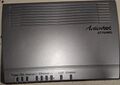
Top of modem
-
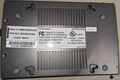
Bottom of Modem
-
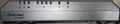
Front of Modem
-
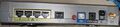
Back of modem
