Samsung SyncMaster 940MW: Difference between revisions
Jump to navigation
Jump to search
No edit summary |
|||
| (6 intermediate revisions by the same user not shown) | |||
| Line 20: | Line 20: | ||
*Leaking caps, usually 2ea 820µF 25v Caps | *Leaking caps, usually 2ea 820µF 25v Caps | ||
====Solutions==== | ====Solutions==== | ||
*Replace all caps | *Replace all caps except for 150 µF Cap | ||
== Disassembly Notes == | == Disassembly Notes == | ||
| Line 33: | Line 33: | ||
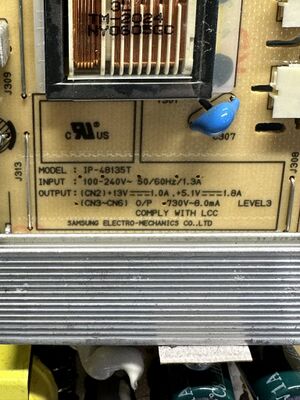
Power Supply Board Model Number IP-48135T<br> | Power Supply Board Model Number IP-48135T<br> | ||
[[File:940MW PS Board Model.jpeg|Main Board Model Number|thumb|none]] | |||
[[File:940MW PS w-labels.jpeg.jpg|Capacitor Locations|thumb|none]] | |||
{| class="wikitable sortable" | {| class="wikitable sortable" | ||
| Line 168: | Line 170: | ||
|Thru Hole | |Thru Hole | ||
|18.00mm | |18.00mm | ||
| | |37.00mm | ||
|7.50mm | |7.50mm | ||
|105 °C | |105 °C | ||
| Line 176: | Line 178: | ||
|Usually don't need to replace | |Usually don't need to replace | ||
|} | |} | ||
== Related Links == | == Related Links == | ||
Latest revision as of 23:23, 28 January 2024
- For more information, see this article's corresponding Wikipedia page: Device.
Samsung SyncMaster 940MW
| Preliminary Information | |
|---|---|
| Release Year | 2006 |
| Leak Risk | High |
| Batteries | None |
| Mounting Technology | Through Hole |
| Capacitor Types | Aluminum Electrolytic |
| Destructive Entry | No |
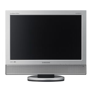
19" 1440x900 60Hz LCD Panel Computer Monitor with VGA, DVI, Composite, Componet, S-Video, SCART inputs. Internal power supply.
Known Issues
Symptom or Problem Encountered
Causes
- Leaking caps, usually 2ea 820µF 25v Caps
Solutions
- Replace all caps except for 150 µF Cap
Disassembly Notes
1. 4 Screws for the base support
2. 3 Case Screws, 2ea in lower corners and 1ea behind base support area
3. Using a plastic spudger, separate case from bottom to top
4. Remove all screws from metal sheld
5. Power Supply is on the left as looking from the rear
Original Parts
Basic PCB Name
Power Supply Board Model Number IP-48135T


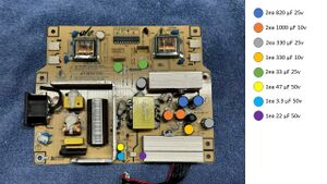
| RefDes | Qty | Capacitance | Voltage | Mount | Diameter/Size | Height | Lead Spacing | Temp | Type | Brand | Series | Comment |
|---|---|---|---|---|---|---|---|---|---|---|---|---|
| 2 | 1000 µF | 10v | Thru Hole | 10mm | 14.00mm | 5.00mm | 105 °C | Electrolytic | ||||
| 2 | 820 µF | 25v | Thru Hole | 10mm | 22.00mm | 5.00mm | 105 °C | Electrolytic | ||||
| 1 | 330 µF | 10v | Thru Hole | 8mm | 13.00mm | 3.50mm | 105 °C | Electrolytic | ||||
| 2 | 330 µF | 25v | Thru Hole | 10mm | 14.00mm | 5.00mm | 105 °C | Electrolytic | ||||
| 1 | 47 µF | 50v | Thru Hole | 6.3mm | 12.50mm | 5.00mm | 105 °C | Electrolytic | ||||
| 2 | 33 µF | 25v | Thru Hole | 6.3mm | 7.00mm | 2.50mm | 105 °C | Electrolytic | ||||
| 1 | 22 µF | 50v | Thru Hole | 5.00mm | 12.00mm | 5.00mm | 105 °C | Electrolytic | ||||
| 1 | 3.3 µF | 50v | Thru Hole | 4.00mm | 7.00mm | 2.50mm | 105 °C | Electrolytic | ||||
| 1 | 150 µF | 450v | Thru Hole | 18.00mm | 37.00mm | 7.50mm | 105 °C | Electrolytic | Usually don't need to replace |
Related Links
User Manual
YouTube Repair Video by glasstronic
