NeXTStation Turbo Color (ADB): Difference between revisions
Chartreuse (talk | contribs) (Initial information on mainboard capacitors and replacement.) |
m (added hardware information) |
||
| (4 intermediate revisions by 2 users not shown) | |||
| Line 3: | Line 3: | ||
{{InfoboxDevice | {{InfoboxDevice | ||
|Title = NeXTStation Turbo Color (ADB) | |Title = NeXTStation Turbo Color (ADB) | ||
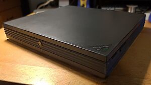
|Picture = | |Picture =[[File:NextstationTC1.jpg|thumb|NeXTStation Turbo Color]] | ||
|Release Year = 1992/1993 | |Release Year = 1992/1993 | ||
|Mounting Technology = Through Hole, SMD | |Mounting Technology = Through Hole, SMD | ||
| Line 10: | Line 10: | ||
|Batteries = BR-2/3A Lithium Primary 3V | |Batteries = BR-2/3A Lithium Primary 3V | ||
|Destructive Entry = No | |Destructive Entry = No | ||
}} | |CPU=Motorola 68040 (33 MHz)|Memory=Four 72-pin SIMM slots (up to 128 MB) (stock 16 MB)}} | ||
==Known Issues== | ==Known Issues== | ||
==Disassembly Notes== | ==Disassembly Notes== | ||
Disassembling the NeXTStation is extremely simple, and is designed for servicing. To remove the motherboard only a total of 4 screws need to be removed. | Disassembling the NeXTStation is extremely simple, and is designed for servicing. To remove the motherboard only a total of 4 screws need to be removed. | ||
| Line 21: | Line 19: | ||
Undo the single Phillips screw on the back. Then lift the top cover up and off. | Undo the single Phillips screw on the back. Then lift the top cover up and off. | ||
Once inside, disconnect the SCSI ribbon cable and molex power for the hard drive from the motherboard. | Once inside, disconnect the SCSI ribbon cable and molex power for the hard drive from the motherboard. | ||
Remove the single Philips screw holding the hard drive mount in place. Lift up from the screw side and the hard drive tray will rotate, hinging on the opposite side before lifting out. | Remove the single Philips screw holding the hard drive mount in place. Lift up from the screw side and the hard drive tray will rotate, hinging on the opposite side before lifting out. | ||
| Line 31: | Line 29: | ||
Disconnect the 2 pin fan header, and the power supply connector. Both lift straight up, the PSU one may take some force. Remember to hold down the motherboard while doing so. | Disconnect the 2 pin fan header, and the power supply connector. Both lift straight up, the PSU one may take some force. Remember to hold down the motherboard while doing so. | ||
Finally remove the single Phillips screw holding down the motherboard, and lift from the front edge. The board will come right out, mind the connectors at the back. | Finally remove the single Phillips screw holding down the motherboard, and lift from the front edge. The board will come right out, mind the connectors at the back. | ||
==Original Parts== | ==Original Parts== | ||
===Mainboard=== | ===Mainboard=== | ||
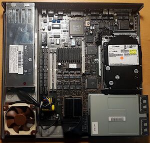
[[File:NextstationTC2.jpg|alt=Internals with cover removed. (After recapping)|thumb|Internals with cover removed. (After recapping)]] | |||
PN-4244.00 | PN-4244.00 | ||
| Line 44: | Line 42: | ||
NOTE: No components have reference designators and polarity is NOT marked for capacitors. Through hole capacitors should have their positive leg in the square pad hole. When viewed with the connectors at the back, all surface mount capacitors should have the negative stripe to the right, and the through hole ones to the left. | NOTE: No components have reference designators and polarity is NOT marked for capacitors. Through hole capacitors should have their positive leg in the square pad hole. When viewed with the connectors at the back, all surface mount capacitors should have the negative stripe to the right, and the through hole ones to the left. | ||
{| class="wikitable sortable" | {| class="wikitable sortable" | ||
|+Capacitor [[Capacitor Specifications|Specifications]] and | |+Capacitor [[Capacitor Specifications|Specifications]] and [[Part Footprints|Footprint]] Information | ||
!RefDes | !RefDes | ||
!Qty | !Qty | ||
| Line 81: | Line 79: | ||
|105°C | |105°C | ||
|Electrolytic | |Electrolytic | ||
|Matsushita | |Matsushita/Panasonic | ||
|HFQ | |HFQ | ||
|} | |} | ||
==Replacement Parts== | ==Replacement Parts== | ||
===Mainboard=== | ===Mainboard=== | ||
| Line 96: | Line 93: | ||
|SMD | |SMD | ||
|8 | |8 | ||
|UCW1C470MCL1GS | |UCW1C470MCL1GS / 865090343005 / UWT1E470MCL6GS | ||
|[https://www.digikey.com/en/products/detail/nichicon/UCW1C470MCL1GS/2549773 | |[https://www.digikey.com/en/products/detail/nichicon/UCW1C470MCL1GS/2549773 DigiKey] [https://www.mouser.com/ProductDetail/Wurth-Elektronik/865090343005?qs=0KOYDY2FL285seFxpaRTOQ%3D%3D Mouser] [https://www.lcsc.com/product-detail/Aluminum-Electrolytic-Capacitors-SMD_Nichicon-UWT1E470MCL6GS_C445066.html LCSC] | ||
|- | |- | ||
|TH | |TH | ||
|3 | |3 | ||
|EEU-FC1V221 | |EEU-FC1V221 / 25YXJ220M6.3X11 | ||
|[https://www.digikey.com/en/products/detail/panasonic-electronic-components/EEU-FC1V221/266306 | |[https://www.digikey.com/en/products/detail/panasonic-electronic-components/EEU-FC1V221/266306 DigiKey] [https://www.mouser.com/ProductDetail/Panasonic/EEU-FC1V221?qs=iiQS8Qu7XZTt1rQb8bsJjg%3D%3D Mouser] [https://www.lcsc.com/product-detail/Aluminum-Electrolytic-Capacitors-Leaded_Rubycon-25YXJ220M6-3X11_C88729.html LCSC] | ||
|} | |} | ||
Replacement TH parts number is 35v instead of 25v, but works fine and is low ESR. | Replacement TH parts number is 35v instead of 25v, but works fine and is low ESR. | ||
''If parts are not available or different selection is preferred, you can use the values in the [[#Original_Parts|Original Parts]] section to perform a parametric search'' | ''If parts are not available or different selection is preferred, you can use the values in the [[#Original_Parts|Original Parts]] section to perform a parametric search'' | ||
==Related Links== | ==Related Links== | ||
*https://lowendmac.com/next/nscturbo.html | *https://lowendmac.com/next/nscturbo.html | ||
* | * | ||
==References== | ==References== | ||
<references /> | <references /> | ||
[[Category:Computer]] | |||
[[Category:1990s]] | |||
Latest revision as of 21:29, 3 April 2023
- For more information, see this article's corresponding Wikipedia page: NeXTstation.
| Preliminary Information | |
|---|---|
| Release Year | 1992/1993 |
| Leak Risk | High |
| Batteries | BR-2/3A Lithium Primary 3V |
| Mounting Technology | Through Hole, SMD |
| Capacitor Types | Aluminum Electrolytic, Ceramic |
| Destructive Entry | No |
| Hardware Specifications | |
| CPU | Motorola 68040 (33 MHz) |
| Memory Capacity | Four 72-pin SIMM slots (up to 128 MB) (stock 16 MB) |
Known Issues
Disassembly Notes
Disassembling the NeXTStation is extremely simple, and is designed for servicing. To remove the motherboard only a total of 4 screws need to be removed.
First unplug the unit, removing any other cables or adapters connected to it.
Undo the single Phillips screw on the back. Then lift the top cover up and off.
Once inside, disconnect the SCSI ribbon cable and molex power for the hard drive from the motherboard.
Remove the single Philips screw holding the hard drive mount in place. Lift up from the screw side and the hard drive tray will rotate, hinging on the opposite side before lifting out.
Disconnect the floppy ribbon from the mainboard (there is no separate power connector, power is over this ribbon).
Remove the single Phillips screw holding the floppy drive in place, and lift and rotate it the same as the hard drive to remove.
Disconnect the 2 pin fan header, and the power supply connector. Both lift straight up, the PSU one may take some force. Remember to hold down the motherboard while doing so.
Finally remove the single Phillips screw holding down the motherboard, and lift from the front edge. The board will come right out, mind the connectors at the back.
Original Parts
Mainboard

PN-4244.00
Only the SMD caps seem to leak, the through-hole ones appeared just fine with no sign of leakage below them when removed. However they are very easy to desolder and there are only 3, so the cost of doing so is minimal.
While a multi-layer board, the through hole capacitors are very easy to desolder owing to large through holes. You are very unlikely to damage the board recapping with only basic tools.
NOTE: No components have reference designators and polarity is NOT marked for capacitors. Through hole capacitors should have their positive leg in the square pad hole. When viewed with the connectors at the back, all surface mount capacitors should have the negative stripe to the right, and the through hole ones to the left.
| RefDes | Qty | Capacitance | Voltage | Mount | Diameter/Size | Height | Pin Pitch | Temp | Type | Brand | Series |
|---|---|---|---|---|---|---|---|---|---|---|---|
| SMD | 8 | 47uF | 16v | SMD | 6.30mm | 7.00mm | 6.60mm x 6.60mm | Electrolytic | Unknown (Marked w with overbar) (W2) | W2 | |
| TH | 3 | 220uF | 25v | Through Hole | 10.00mm | 13.00mm | 5.00mm | 105°C | Electrolytic | Matsushita/Panasonic | HFQ |
Replacement Parts
Mainboard
| RefDes | Qty | Compatible Part Number | Order Links |
|---|---|---|---|
| SMD | 8 | UCW1C470MCL1GS / 865090343005 / UWT1E470MCL6GS | DigiKey Mouser LCSC |
| TH | 3 | EEU-FC1V221 / 25YXJ220M6.3X11 | DigiKey Mouser LCSC |
Replacement TH parts number is 35v instead of 25v, but works fine and is low ESR.
If parts are not available or different selection is preferred, you can use the values in the Original Parts section to perform a parametric search
