Thermaltake Purepower-480D: Difference between revisions
Amminadabz (talk | contribs) (Initial entry. Overview, disassembly notes, review link.) |
No edit summary |
||
| (6 intermediate revisions by 2 users not shown) | |||
| Line 1: | Line 1: | ||
{{DeviceAlerts}} | {{DeviceAlerts}} | ||
{{InfoboxDevice | {{InfoboxDevice | ||
|Title = | |Title = Purepower-480D | ||
|Picture = | |Picture =Thermaltake Purepower-480D.jpg | ||
|Release Year = | |Release Year = 2003 | ||
|Mounting Technology = Through Hole | |Mounting Technology = Through Hole | ||
|Capacitor Types = Aluminum Electrolytic, Tantalum, Ceramic, | |Capacitor Types = Aluminum Electrolytic, Tantalum, Ceramic, Paper(?) | ||
|Leak Risk = Medium | |Leak Risk = Medium | ||
|Batteries = None | |Batteries = None | ||
| Line 12: | Line 12: | ||
The Thermaltake Purepower-480D is a high end 480W ATX-12V PSU from the mid 2000s. It included two built in fans, controllable by a knob mounted in a PCI slot or 5.25" bay, and could be found in both silver and black cases, both with gold colored fan grills. | The Thermaltake Purepower-480D is a high end 480W ATX-12V PSU from the mid 2000s. It included two built in fans, controllable by a knob mounted in a PCI slot or 5.25" bay, and could be found in both silver and black cases, both with gold colored fan grills. | ||
==Known Issue== | ==Known Issue== | ||
=== | ===Bulging=== | ||
The electrolytic capacitors C13, C15, C16, and C37 are at elevated risk of bulging or failure. Replacement is advised. | |||
==Disassembly Notes== | ==Disassembly Notes== | ||
The author found it necessary to cut the four wires leading from the | The author found it necessary to cut the four wires leading from the PCB to the socket and power switch in order to remove the PCB from the case. You may want to mark one of the pair of brown wires for reassembly. It is also best to remove both fans. | ||
Upon reassembly, you can re-attach these wires using spade crimp connectors and heat-shrink tubing, or by replacing the wires and re-soldering them to the plug and switch. Make sure that the wires do not obstruct either of the fans before closing the case. | |||
==Original Parts== | ==Original Parts== | ||
=== | ===Main PCB=== | ||
'' | ''NO380, Revision A4'' | ||
Partial listing, only the parts deemed worth replacing. | |||
{| class="wikitable sortable" | {| class="wikitable sortable" | ||
|+Capacitor [[Capacitor Specifications|Specifications]] and [[Part Footprints|Footprint]] Information | |+Capacitor [[Capacitor Specifications|Specifications]] and [[Part Footprints|Footprint]] Information | ||
| Line 38: | Line 38: | ||
!Series | !Series | ||
|- | |- | ||
| | |C13, C15 | ||
| | |2 | ||
| | |3300 µF | ||
| | |6.3 V | ||
| | |Through-hole | ||
| | |10.2 mm | ||
| | |25.5 mm | ||
| | |5 mm | ||
| | |105 °C | ||
| | |Aluminum Electrolytic | ||
| | |JENPO | ||
| | |CE-LE | ||
|- | |||
|C16, C37 | |||
|2 | |||
|470 μF | |||
|16 V | |||
|Through-hole | |||
|8.2 mm | |||
|11.7 mm | |||
|3.3 mm | |||
|105 °C | |||
|Aluminum Electrolytic | |||
|TEAPO | |||
|A3 | |||
|} | |} | ||
==Replacement Parts== | ==Replacement Parts== | ||
| Line 60: | Line 73: | ||
!Order Links | !Order Links | ||
|- | |- | ||
| | |C13, C15 | ||
| | |2 | ||
| | |ECA-0JM332 / 10YXJ3300M12.5X20 | ||
|[https://www.digikey.com/ | |[https://www.digikey.com/en/products/detail/panasonic-electronic-components/ECA-0JM332/244976 DigiKey] [https://www.mouser.com/ProductDetail/667-ECA-0JM332 Mouser] [https://www.lcsc.com/product-detail/Aluminum-Electrolytic-Capacitors-Leaded_Rubycon-10YXJ3300M12-5X20_C1595940.html LCSC] | ||
|- | |||
|C16, C37 | |||
|2 | |||
|EST477M016AG4EA / 860080374013 / 16YXJ470M8X11.5 | |||
|[https://www.digikey.com/en/products/detail/w%C3%BCrth-elektronik/860080374013/5727236 DigiKey] [https://www.mouser.com/ProductDetail/80-EST477M016AG4EA Mouser] [https://www.lcsc.com/product-detail/Aluminum-Electrolytic-Capacitors-Leaded_Rubycon-16YXJ470M8X11-5_C432444.html LCSC] | |||
|} | |} | ||
''If parts are not available or different selection is preferred, you can use the values in the [[#Original_Parts|Original Parts]] section to perform a parametric search.'' | ''If parts are not available or different selection is preferred, you can use the values in the [[#Original_Parts|Original Parts]] section to perform a parametric search.'' | ||
===Kits=== | ===Kits=== | ||
* | *[https://www.mouser.com/ProjectManager/ProjectDetail.aspx?AccessID=596c955864 Mouser project] | ||
[[File:Thermaltake Purepower-480D internal.jpg|alt=Power Supply Internals|none|thumb|Power Supply Internals]] | |||
==Related Links== | ==Related Links== | ||
*An [https://www.anandtech.com/show/1124/6 AnandTech review] from the period, including internal pictures and specs. | *An [https://www.anandtech.com/show/1124/6 AnandTech review] from the period, including internal pictures and specs. | ||
==References== | ==References== | ||
<references /> | <references /> | ||
[[Category: | [[Category:Power Supply]] | ||
[[Category:2000s]] | |||
[[Category:Computer Part]] | |||
__INDEX__ | |||
[[Category:WorkNeeded:OriginalParts]] | [[Category:WorkNeeded:OriginalParts]] | ||
Latest revision as of 21:57, 15 December 2023
| This device is in the WorkNeeded:OriginalParts category because it was flagged as missing information on the original parts. It may have replacement parts listed but those cannot be assumed to be identical to the originals. If you have a list of the original parts, please feel free to add them by copying the relevant table from EditorsToolbox:Tables |
| Preliminary Information | |
|---|---|
| Release Year | 2003 |
| Leak Risk | Medium |
| Batteries | None |
| Mounting Technology | Through Hole |
| Capacitor Types | Aluminum Electrolytic, Tantalum, Ceramic, Paper(?) |
| Destructive Entry | No |
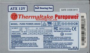
The Thermaltake Purepower-480D is a high end 480W ATX-12V PSU from the mid 2000s. It included two built in fans, controllable by a knob mounted in a PCI slot or 5.25" bay, and could be found in both silver and black cases, both with gold colored fan grills.
Known Issue
Bulging
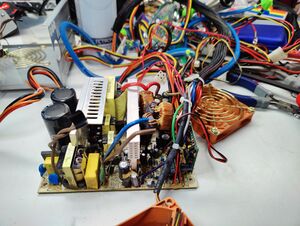
The electrolytic capacitors C13, C15, C16, and C37 are at elevated risk of bulging or failure. Replacement is advised.
Disassembly Notes
The author found it necessary to cut the four wires leading from the PCB to the socket and power switch in order to remove the PCB from the case. You may want to mark one of the pair of brown wires for reassembly. It is also best to remove both fans.
Upon reassembly, you can re-attach these wires using spade crimp connectors and heat-shrink tubing, or by replacing the wires and re-soldering them to the plug and switch. Make sure that the wires do not obstruct either of the fans before closing the case.
Original Parts
Main PCB
NO380, Revision A4
Partial listing, only the parts deemed worth replacing.
| RefDes | Qty | Capacitance | Voltage | Mount | Diameter/Size | Height | Lead Spacing | Temp | Type | Brand | Series |
|---|---|---|---|---|---|---|---|---|---|---|---|
| C13, C15 | 2 | 3300 µF | 6.3 V | Through-hole | 10.2 mm | 25.5 mm | 5 mm | 105 °C | Aluminum Electrolytic | JENPO | CE-LE |
| C16, C37 | 2 | 470 μF | 16 V | Through-hole | 8.2 mm | 11.7 mm | 3.3 mm | 105 °C | Aluminum Electrolytic | TEAPO | A3 |
Replacement Parts
Basic PCB Name
| RefDes | Qty | Compatible Part Number | Order Links |
|---|---|---|---|
| C13, C15 | 2 | ECA-0JM332 / 10YXJ3300M12.5X20 | DigiKey Mouser LCSC |
| C16, C37 | 2 | EST477M016AG4EA / 860080374013 / 16YXJ470M8X11.5 | DigiKey Mouser LCSC |
If parts are not available or different selection is preferred, you can use the values in the Original Parts section to perform a parametric search.
Kits

Related Links
- An AnandTech review from the period, including internal pictures and specs.
