Chauvet Strike 1: Difference between revisions
Millstream (talk | contribs) No edit summary |
Millstream (talk | contribs) mNo edit summary |
||
| Line 1: | Line 1: | ||
{{DeviceAlerts}}The Chauvet STRIKE 1 is an outdoor | {{DeviceAlerts}}The Chauvet STRIKE 1 is an outdoor rated blinder powered by a 230 W warm white LED source. It is also a strobe and a wide area floodlight. | ||
==Known Issues== | ==Known Issues== | ||
===Symptom or Problem Encountered=== | ===Symptom or Problem Encountered=== | ||
Non functioning light. No display on the control panel. | Non functioning light. No display on the control panel. | ||
I was told it's | I was told it's a failed PSU. It wasn't. | ||
====Causes==== | ====Causes==== | ||
*Shorted diode on controller board. | *Shorted diode on controller board. | ||
| Line 26: | Line 26: | ||
I repaired two of these with identical faults. | I repaired two of these with identical faults. | ||
== Re-assembly == | |||
Make sure the seal is seated correctly as you re-seat the module. | |||
Do not over tighten the screws, bearing in mind that the threads in the aluminium are relatively soft and possibly already damaged by corrosion. | |||
Use some anti-seize compound if you have any. A light greasing may help to prevent further corrosion but can aggravate over tightening. | |||
==Original Parts== | ==Original Parts== | ||
===Basic PCB Name=== | ===Basic PCB Name=== | ||
| Line 36: | Line 44: | ||
!Current | !Current | ||
![https://caps.wiki/wiki/Part_Footprints Mount] | ![https://caps.wiki/wiki/Part_Footprints Mount] | ||
! | !Footprint | ||
|- | |- | ||
|SS310 | |SS310 | ||
Revision as of 12:42, 16 July 2023
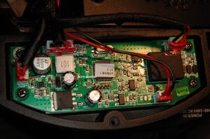
The Chauvet STRIKE 1 is an outdoor rated blinder powered by a 230 W warm white LED source. It is also a strobe and a wide area floodlight.
Known Issues
Symptom or Problem Encountered
Non functioning light. No display on the control panel.
I was told it's a failed PSU. It wasn't.
Causes
- Shorted diode on controller board.
Solutions
- Replace a £0.60 diode.
Disassembly Notes
These are outdoor lights and the cap head screws may have corrosion in the aluminium housing. Use penetrating oil if possible.
Remove the three cap head screws holding the display and control panel housing taking care to retain the washers.
The panel assembly will lift out. If the fault is as described the connectors can remain undisturbed. Some of the zip ties had sharp pointy ends, so take care with those.

Diagnosis
Without mains power connected check for a short across D2, adjacent to the inductor.
If short, lift one side of the diode (or remove it completely) and check the diode and the solder pads. In my case the short on the board went away.
If that's not the the fault, plug in the mains power and check the DC voltage into the board. The voltage to the board is 63V DC.
Replacing the diode fixed the fault. But as to what caused the failure in the first place?
I repaired two of these with identical faults.
Re-assembly
Make sure the seal is seated correctly as you re-seat the module.
Do not over tighten the screws, bearing in mind that the threads in the aluminium are relatively soft and possibly already damaged by corrosion.
Use some anti-seize compound if you have any. A light greasing may help to prevent further corrosion but can aggravate over tightening.
Original Parts
Basic PCB Name
Controller board.
| RefDes | Qty | Voltage | Current | Mount | Footprint |
|---|---|---|---|---|---|
| SS310 | 1 | 100 | 3A | SMD | DO214 |
Replacement Parts
| RefDes | Qty | Description | Compatible Part Number | Order Links |
|---|---|---|---|---|
| SS310 | 1 | Schottky Diode 100V 3A |
If parts are not available or different selection is preferred, you can use the values in the Original Parts section to perform a parametric search.