Disassembly:IBM 8513 VGA Monitor, 12"
Details listed below come from the official "PS/2 Displays Maintenance Manual"
You can download a copy from here: http://ohlandl.ipv7.net/books/Ps2displ.boo
This is saved in IBM's .boo format. In order to read it, you will require to use IBM Softcopy Reader for Windows. It can be downloaded from here: https://www.ibm.com/support/pages/ibm-softcopy-reader-windows-v40-0
1.3.1 Tilt Swivel Stand
The tilt swivel stand is the same for most models, but some have a
different method of attachment and some lift as well as tilt and swivel.
1. Power off the system and the display, and disconnect all cables. (See
"Powering Off the System" in topic 1.1.3.)
2. Place the display on its front cover, protected with a soft cloth or
similar material.
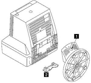
3. Remove the thumbscrew 1 , disengage the locating hooks 2 , and move
the tilt swivel stand away from the display.

Figure 3-1. Removing the Tilt Swivel Stand
Other displays have a tilt swivel stand that is held on with two release
clips. For those types of stands, use these instructions after powering
off the system and removing all cables.
1. Place the display on a flat surface, ensuring that there is sufficient
space to set the display down after removing from the stand.
2. Press the two release clips at the front of the stand assembly.
3. Pull the display forward from the tilt swivel stand.
4. Lift the display from the stand and place it on a flat surface.
Replacement:
Replace the tilt swivel stand by using these instructions in reverse
order.
Rear Cover, Type 1
The removal procedures for this type of rear cover are:
1. Power off the system and the display, and disconnect all cables (see
"Powering Off the System" in topic 1.1.3).
2. Remove the tilt swivel stand (see "Tilt Swivel Stand" in topic 1.3.1),
or the lift tilt swivel stand (see "Lift Tilt Swivel Stand" in
topic 1.3.2).
3. Refer to Figure 3-3.
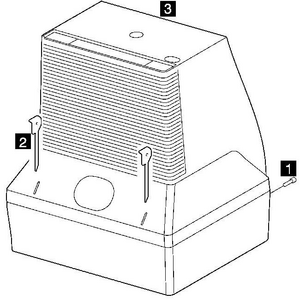
4. Remove the two securing screws 1 from the rear cover.
Some models have only a single hex head screw on the bottom of the display
that must be removed. Additionally, these covers may require that you
unclip two plastic closing plates from the interface cable to allow the
plug to pass through the cover.
5. Insert the delatching tools 2 into the slots to release the
fasteners.
6. Ease the rear cover 3 away from the display, after disengaging the
signal cable from the retention slot.

PICTURE 7
Figure 3-3. Removing the Rear Cover, Type 1
Replacement:
Ensure that the securing arms of the card tray assembly are latched into
the front cover.