VIA EPIA CN Mini ITX PC
| This device is in the WorkNeeded:OriginalParts category because it was flagged as missing information on the original parts. It may have replacement parts listed but those cannot be assumed to be identical to the originals. If you have a list of the original parts, please feel free to add them by copying the relevant table from EditorsToolbox:Tables |
| This device is in the WorkNeeded:ReplacementParts category because it was flagged as missing information on replacement parts. If it has the original parts listed you may be able to search for replacements using the parametric searches available from parts distributors. If you have or make a list of replacement parts, please feel free to add them by copying the relevant table from EditorsToolbox:Tables |
| This device is in the WorkNeeded:General category because it was flagged as missing general information about the device. The information may be incomplete, using default text, or inaccurate and should be verified with external sources if possible. If you can add or correct information on this page, please feel free to edit it and do so. |
| Preliminary Information | |
|---|---|
| Release Year | 2012 |
| Leak Risk | Medium |
| Batteries | CR2032 |
| Mounting Technology | Through Hole, SMD |
| Capacitor Types | Aluminum Electrolytic |
| Destructive Entry | No |
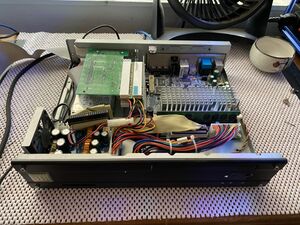
The VIA EPIA CN is a Mini ITX mini PC based on the VIA C7 processor.
Processor: VIA C7 @ 1 GHz (x86 w/PAE)
Chipset: VIA CN700 North Bridge, VIA VT8237R-series South Bridge
Graphics: Integrated C-Pro AGP with MPEG-2 Acceleration
Audio: VIA VT1618 8-channel AC'97 codec
Memory: 1 x 240-pin DDR2-533 (PC2-4200U DIMM (maximum of 1 GB)
Slots: 1 x PCI (broken out to 2 x PCI using riser card)
IDE: 2 x UltraDMA 133/100 controllers
LAN: VIA VT6103 10/100 Ethernet
TV Out: VIA VT1625 HDTV Encoder
Known Issues
Symptom or Problem Encountered
Machine powers down unexpectedly and/or is generally unstable. Out of spec values for voltage rails are shown In the PC Health Status screen of the BIOS.
Causes
- Failing capacitors on the power supply board and/or a failing power brick
Solutions
- Replace capacitors on the power supply board. May also need to replace the power brick.
Original Parts
Power Brick
This device came with a 19 V 4.74 A power brick. Barrel plug is 5.5 mm OD x 2.1 mm ID, and is center (tip) positive.
Power Supply Board

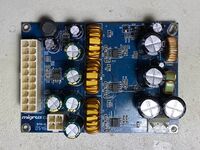
Power supply board is labeled "Migrus C5" and is located in the front left corner of the case.
| RefDes | Qty | Capacitance | Voltage | Mount | Diameter/Size | Height | Lead Spacing | Temp | Type |
|---|---|---|---|---|---|---|---|---|---|
| EC1, EC3, EC7, EC11 | 4 | 2200 µF | 25 V | Through Hole | 13 mm | 22 mm | 6 mm | 105 °C | Electrolytic |
| EC12 | 1 | 100 µF | 25 V | Through Hole | 6.5 mm | 7.5 mm | 2.5 mm | 105 °C | Electrolytic |
| EC13 | 1 | 680 µF | 10 V | Through Hole | 8.2 mm | 12.7 mm | 4 mm | 105 °C | Electrolytic |
| EC2, EC6, EC8, EC9, EC10 | 5 | 1500 µF | 16 V | Through Hole | 10.3 mm | 21 mm | 5.5 mm | 105 °C | Electrolytic |
| EC4, EC5 | 2 | 470 µF | 16 V | Through Hole | 8.25 mm | 12.5 mm | 4 mm | 105 °C | Electrolytic |
Replacement Parts
Power brick
Any 5.5/2.1mm center (tip) positive power brick rated at 19 V and at least 4.74 A should work. The author of this page is using this Nobsound power adapter and it is working well.
Power Supply Board
There is a fair bit of wiggle room on and above the board, so you can fudge a little on the cap dimensions. In particular, the cap they used for EC12 was a very short "low profile" one which is hard to find, and was easily replaced with another (more "normal" sized) capacitor of the same values.
