Mains Power
| WARNING Mains powered devices contain potentially lethal hazards or can become lethal hazards if not correctly repaired which may result in death or serious injury. Ensure you fully understand the content of this page before attempting to disassemble or repair a mains powered device. Do not attempt to disassemble or repair a mains powered device unless you understand how to do so safely. |
| NOTE The content of this Wiki is community contributed and is a continuous work-in-progress and as such no guarantees that this information is complete, accurate or applicable can be made. Caps Wiki and its owner/operator and contributors assume no liability for actions taken based on this information. |
Mains power (often called line, active, hot or AC) refers to the AC power at the final stage of the electrical grid that is run into most buildings and is available at wall outlets. The voltage used varies throughout the world however in North America the standard is 110 - 127 V AC while Europe is 220 - 240 V AC. There is significant danger in coming into contact with mains as the only limit to the current is a breaker or fuse in the service box for the building which is designed to prevent damage to the building's wiring, not prevent damage to connected devices or electrocution. As such devices with exposed mains power have inherent hazards both when they are powered or were recently powered.
Devices with Separated Mains Voltage Power Supplies

Some mains powered devices, especially more modern ones, may have their hazardous high voltage mains power supply separated from the rest of the low voltage circuity. Examples are; a separate external sealed brick power supply, an internal closed frame power supply or an internal open frame power supply with removable plastic covers.
Live or Hot Components
Mains Connected Chassis
Some devices such as CRT displays or televisions or radios may have been designed with a live chassis that is connected to mains power. This means touching the chassis while having contact with either neutral or mains earth can complete a circuit and result in a significant electrical shock. These also pose a hazard for diagnostics and can lead to other difficulties such as finding a suitable DC ground reference for taking measurements.
Non-Isolated Mains Power Supplies
- Those power supplies may generate low voltages however they are not isolated but instead are referenced to mains earth which can result in a severe electric shock if touched.
Mains Voltage Capacitors

Mains Bulk Capacitors
Mains bulk capacitors are present in many new and old devices, most notably the vast majority of general purpose AC-to-DC power supplies are SMPS (Switch Mode Power Supplies), those power supplies rely on rectifying the mains input voltage from AC into DC which is stored in bulk capacitors. This is done to allow a transistor to switch this DC through a transformer at much higher frequencies (often 100 kHz to 1 MHz) than the grid (50 or 60 Hz), this allows the magnetics (eg. transformer) in the power supply to be smaller, lighter, cheaper and more efficient. However those mains voltage bulk capacitors can be rather large on high powered devices to improve regulation performance and increase hold-up time during grid brownouts, because of this those large mains voltage capacitors can pose a shock hazard even after the device has been powered off due to the charge stored in those capacitors.
Discharging Mains Bulk Capacitors
Most modern devices include bleeder resistors to discharge those capacitors however this can take tens of minutes and those resistors can fail. Because of this you should always discharge mains bulk capacitors before touching a PCB after it has been powered on. To discharge a capacitor manually use an insulated tool such as plastic handled pliers to place a resistor directly across the pins of the capacitor, this will discharge the capacitor over a longer period of time and avoid damaging the capacitor or metal tool due to a sudden discharge. A 100 kΩ 1/4 W resistor can be used to discharge small (<100 µF <450 V) capacitors in under 30 s, when using a lower value resistor or discharging a larger capacitor for a long period a higher power resistor is needed otherwise the resistor may overheat and burn. Some multi-meters have a 'Low-Z' mode which will slowly discharge mains voltage capacitors and provide a readout of the voltage. After this step or on devices where you can visually identify the bleeder resistor across the capacitor and have confidence it is functional you can then bridge the capacitor pins with a metal tool directly. If the device is not connected to mains earth, a non-insulated metal tool can be used as a circuit cannot be made through you however this is generally discouraged.
-
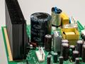
Combined VFD and SMPS PCB with 37 J mains bulk capacitor
-
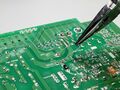
Discharging capacitor with 100 kΩ resistor for 60 s
-
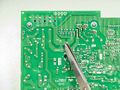
Verifying capacitor is discharged by shorting pins


Voltages Present on Mains Bulk Capacitors
Mains bulk capacitors are charged through rectifiers to the peak mains voltage, however while mains voltage is typically denoted as '230 V AC' this is a contraction of '230 Vrms AC' with 'rms' meaning root mean square. AC voltage is expressed in terms of rms because it allows for easier calculations of power and compatibility with ohms law. An example being 220 Vrms AC × 0.5 A = 110 W. However this means the peak voltage is higher than the rms voltage and this peak voltage is what those capacitors are charged to (240 Vrms AC will be 340 Vp AC and 120 Vrms AC will be 170 Vp AC).
In addition to charging directly through rectifiers some high powered devices like ATX power supplies will have APFC (Active Power Factor Correction), this uses a boost converter to optimize the power extracted from the full AC waveform to improve efficiency and reduce strain on the grid. However this results in the mains bulk capacitor being charged to higher than the mains peak voltage, in some cases up to 400 V DC even in countries where the grid voltage is 100 Vrms AC.
Safety Capacitors
Safety capacitors are often found in the EMI filters of many mains powered devices including many mains power supplies, in-particular SMPSs. Those capacitors are called 'safety' capacitors because their failure can result in a hazardous situation. Because of their placement in circuits often directly across line, neutral and earth or from line and neutral to exposed metalwork they can see very large transient events (eg. lightning transients) and must be rated to withstand those without failing catastrophically. There are two main types of safety capacitors for the two main hazards, class X and class Y. Because of this class X and Y safety capacitors must be replaced with proper safety capacitors of equivalent type, not just any random film or ceramic capacitor.
Those capacitors may also store mains voltages and some more modern devices have bleeder resistors across them however they typically store significantly less energy than even small bulk filter capacitors so shocks are unlikely to be serious.
Class X
Class X capacitors are used where their failure would result in an electrical fire, an example would be in an EMI filter directly on the mains input before any rectification or fuses. Those capacitors are often metallized film capacitors, typically PP (polypropylene) or PET (polyethylene terephthalate) however some older devices may have metallized paper capacitors (such as those manufactured by RIFA) which are known to fail short circuit and should be replaced. Class X1 is rated for higher voltages and better impulse endurance than X2 or X3.
Those capacitors may also be found in certain 'dropper' style power supplies for low power non-isolated applications such as LED bulbs or motion sensors, those capacitors can degrade with time losing capacitance until the device no longer works.


.jpg)
Class Y
Class Y capacitors are used where their failure would result in things the user can touch becoming live at mains voltage, an example is the EMI suppression capacitor across the transformer in a SMPS. Those are often ceramic capacitors that do not fail often, if they fail they fail open circuit almost always. Class Y1 is rated for higher voltages and better impulse endurance than Y2, Y3 or Y4.


Sealed EMI Filters
Sealed EMI filters contain class X and Y capacitors typically along with filter chokes, they are sometimes integrated into IEC power sockets.


Tools and Devices for Working with Mains Powered Devices
Earth Leakage Safety Devices
-

Standard DIN rail mount RCBO protecting an entire circuit
-

North American GFCI protected outlet

